 |
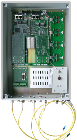
Managed industrial Ethernet switch-second ADS-B MF2.158.008 4G + 2M + 4SHDSL + 2GATEWAY
Industrial switches of the ADS-B series are designed to build branched networks using Gigabit
Ethernet technology using fiber-optic and copper cables on operational-technological
communication networks. In combination with gateways, power and protection devices, they can
effectively organize a departmental technological telecommunication network for communication
and data transmission.
Part number:
Supplier:
JSC SozvezdieDescription
Features:
ADS-B has Ethernet ports:
• two external ports 10Base-T / 100Base-TX / 1000Base-T for cascading switches and connecting
external equipment;
• two external 10Base-T / 100Base-TX ports for connecting local external equipment;
• two internal ports for connecting optical modules SFP 100Base-FX / 1000Base-X;
• four internal Ethernet ports for connecting two 4-channel SHDSL.bis modems;
• two internal Ethernet ports for connecting two gateway modules.
Services are cheapened:
- analog telemechanics at the junction of PM;
- digital telemechanics at the joints "Ethernet", RS-232 / RS-485;
- dispatch communication at the joints of "Ethernet", PM;
- radio cable communication using the base duplex VHF radio station at the junction of the PM;
- remote PBX subscribers (FXO / FXS);
- FE1 traffic transmission, including for PBX trunk lines;
- Association of corporate local area networks at the Ethernet interfaces;
- official communication;
- video surveillance at the Ethernet junction;
- video conferencing at the junction "Ethernet".
External circuits and cables are introduced through pressure glands located on the lower base.
General description:
The ADS-B switch has an industrial design (-40 +50 ° С, Ip66) and is made in a metal case, the
overall dimensions of the switch are 420x300x120mm.
The ADS-B switchboard consists of a baseboard and optical modules optionally installed on it,
SHDSL.bis modems and gateways, as well as optionally: a 220V, 50 Hz power supply unit, a
remote power receiver (DP) board and DP loops, a SHDSL interface for protection devices .
Local equipment can be individual PCs, Ethernet network segments, IP video cameras, process
equipment with Ethernet ports, other switches or network equipment.
SFP optical modules are designed to connect to fiber optic links. The type of module used is
determined based on the requirements of the project: to the transmission speed (100Mbit / s or
1000Mbit / s), to the type of fiber (glass or organic), the number of fibers (one or two), attenuation
(line length from 20 to 200 km), laser wavelength (in case of using xWDM technologies). The
switch can have 1, 2, or no SFP modules installed.
Ethernet ports and bridge features.
Supported Modes: 10HD, 10FD, 100HD, 100FD, 1000FD.
Additional functions: automatic crossover of pairs of port reception and transmission, 802.3x flow
control.
MAC address table size: 1024/8192/8192 entries.
VLAN Support: Port Separated, 4096 802.1Q VLAN.
QOS support: 4 priority queues 8: 4: 2: 1 (FQ) with assignment for: port numbers, IP packet
headers (IPv4, IPv6), VLAN ID (tag VID field), destination and sender MAC addresses. The
insulation voltage of the linear transformer is not worse than 1500V.
4-channel SHDSL.bis modems are designed to connect to physical copper lines. Signal coding and
data formats comply with ITU-T recommendations G.991.2 (SHDSL), G.991.2b (SHDSL bis).
Each modem provides data transmission in one or two directions in one, two or four pairs.
Modem Options:
Transmission Code: TS-RAM4 / 8/16/32/64/128.
The total speed of the digital stream on the line: 200 ... 15312 Kbps.
Data rate in the stream on the line:
Independent port 192 ... 15304 Kbps.
The port as part of the group is 192 ... 11328 Kbps.
Discretization of the choice of speed ... 64 Kbps.
Synchronization mode: ... synchronous, co-directional (For).
Insulation voltage of a linear transformer ... at least 2500V.
There is primary and secondary port protection against surge surges.
The maximum length of the regeneration section in meters when transmitting on one pair:
The data stream can be divided into several SHDSL ports connected in groups.
For example, when transmitting a stream of 2048 kbit / s in 2 pairs (1 in four) of the cable МКС-
1,2, the maximum length of the regeneration section will be 31 km.
In addition to the standard 2-wire transmission mode (in duplex for one pair), a 4-wire transmission
mode with separation of reception and transmission in two pairs is supported. The 4-wire mode is
designed to enable the modem to work together with transmission systems using frequency division
multiplexing (for example, BK / G or K60). The switch can have 1, 2, or no SHDSL.bis modems
installed. You can programmatically lower the power of the signal transmitted by the DSL port to
the line.
Gateways are designed to transfer data through the TCP / IP stack services from interfaces that do
not require operation through a packet-switched environment. For basic applications, there are two
types of gateways:
– A combined gateway for transmitting data in start-stop format from two RS232 or RS485 ports, as
well as the status of two sets of signal circuits (data from sensors). The circuits of each RS232 / 485
port and each set of signal circuits are galvanically isolated and protected;
– Voice gateway for voice traffic (telephone termination).
The switch can have 1, 2, or no gateways installed. Each gateway has its own IP address, due to
which it can work and configure independently of other gateways and from the switch.
In addition, an additional signaling gateway is integrated on the base board of the switch.
The switch and installed gateways are configured remotely using terminal commands via the Telnet
protocol. There is support for the SNMP protocol and WEB management tools. It is possible to
remotely replace software.
The power supply of the switch is universal:
- from a direct current voltage of 48V (from 18V to 72V;
- from an alternating current network of voltage 220 V +22 -33V, 50 Hz;
- from a remote power supply with a stabilized current of 150 mA according to the “pair-pair”
scheme (phantom circuit pairs of a linear cable).
When powered by a power supply source, the built-in controller provides automatic measurement of
consumption and configuration of the circuit to ensure high efficiency of the power supply receiver,
as well as automatic loops to ensure that power is maintained and the communication line is
functioning to the point where the line cable breaks.
Specification
1. Specification_RUS.docx2. Specification_ENG_(2).docx